Vacuum Pumping System
Vacuum pumps
XO-VAC+ contains a vacuum pumping system based on the Pfeiffer HiCube Eco turbo pumping station. It has a Pfeiffer HiPace 80 DN63CF Turbopump backed by a Pfeiffer MVP 015-2 Diaphragm pump.
The HiPace 80 DN63CF Turbopump is mounted directly on the main vacuum chamber and is located in the back box. The MVP 015-2 Diaphragm pump is installed inside the Vacuum Control box.
The datasheets and user manuals are available to download on the Resources page.
flowchart LR
    A[Vacuum Chamber]
    B[Turbopump]
    C[Diaphgram pump]
    D[External Environment]
    A --> B
    B --> C
    C --> D
Vacuum gauge
XO-VAC+ uses a Pfeiffer PKR 361 DN 40 CF-F vacuum gauge. It can measures pressures from 1E-9 to 1E3 hPa. It has a nominal accuracy of 30% and a repeatability of 5% in the pressures between 1E-8 and 1E2 hPa.
Its datasheet and user manual are available to download on the Resources page.
Controller
The Turbo pump is driven by a Pfeiffer TC 110 Electronic Drive Unit. The user interfaces with the TC 110 using the Pfeiffer DCU Display and Operating Unit.
The TC 110 and DCU user manuals are available to download on the Resources page.
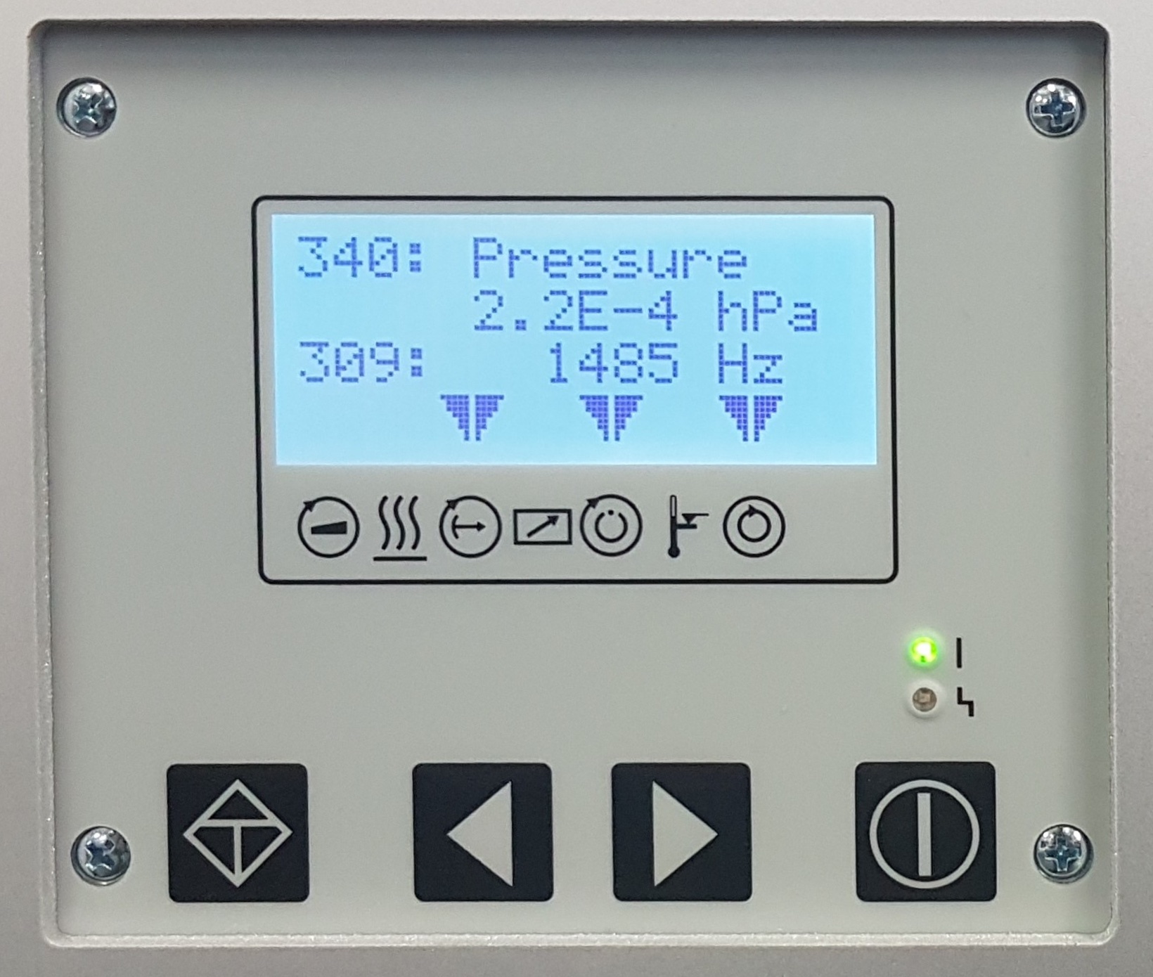
The vacuum pumping system is controlled using the front panel shown below (the DCU). For details on how to operate the pump using the control panel, see the Vacuum System Control page.
Warning
The user is responsible for ensuring the safety of any test regimes carried out using XO-VAC+. XO-VAC+ is a pressure chamber and is only rated for pressures between 0kPa (vacuum) and atmospheric pressure.
Careful consideration should be given to whether the test subject contains any substance which may be inflammable, vapourise, or transform to gaseous phase in a vacuum.
The potential consequences of this include the risk of toxic gasses or smoke being ejected from the vacuum system directly into the laboratory environment, and/or the risk of serious explosion.
Venting
flowchart LR
    A[Vacuum Chamber]
    B[Turbopump]
    E[Ambient Air]
    B --> A
    E --> B
When the vacuum system on XO-VAC+ is vented, the air is released to the surrounding environments without any chemical filter. Which may pose a hazard depending on the chemical and physical behaviour of the payload (see warning above). The exhaust is located inside the Vacuum Control box.
If no inert gas is supplied on the venting inlet, the XO-VAC+ will be vented with the air coming through the venting inlet.
Note
It is recommended to provide dry clean gas (e.g. filtered air) on the venting inlet to reduce the vacuum pumps exposure to dust and to increase their service life.
Warning
The turbopump has to be fully stopped before venting with air. The air goes to the vacuum chamber through the turbopump .
Inert gas venting
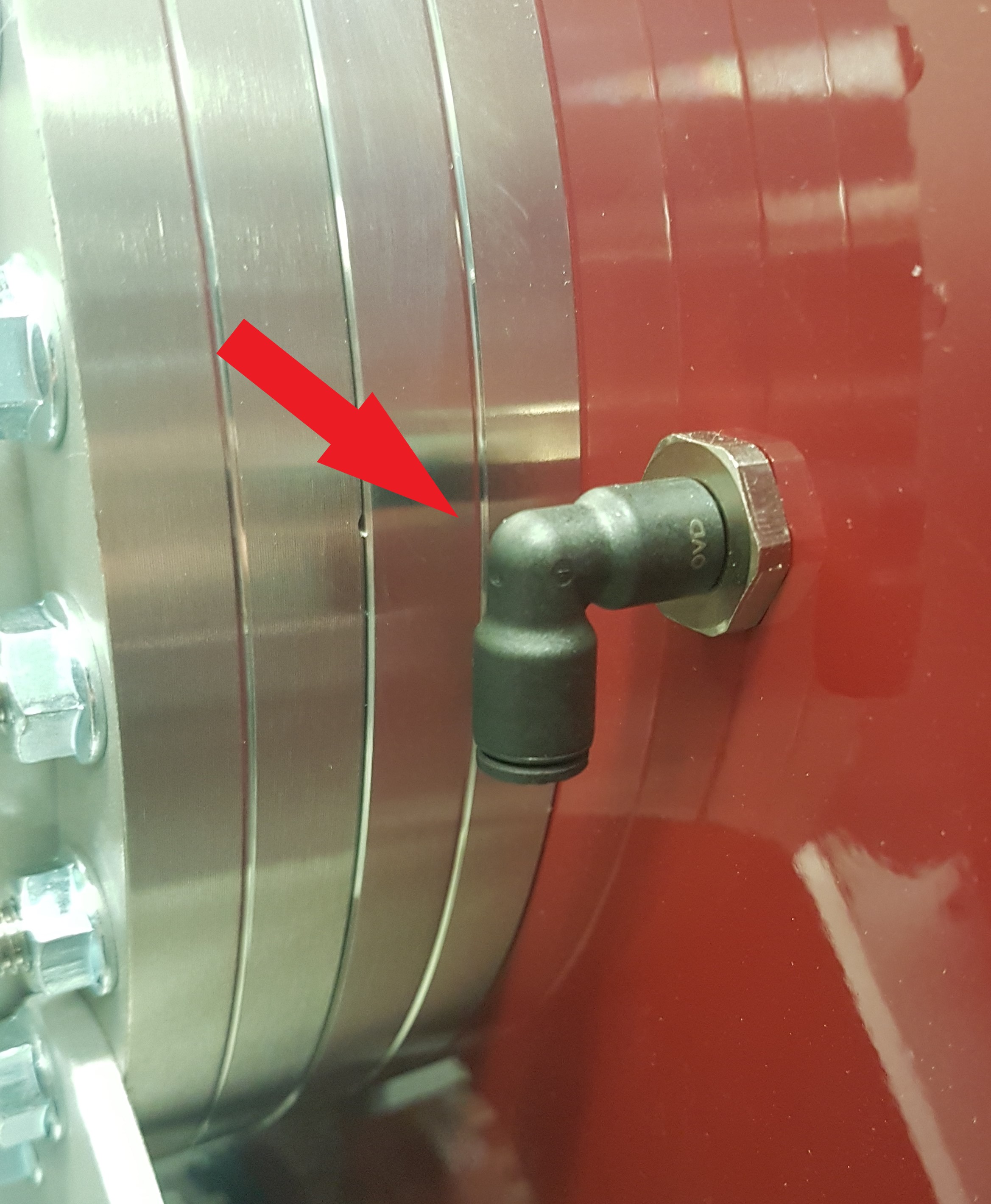
It is possible to vent the XO-VAC+ chamber using inert gases (e.g. nitrogen). A vent nozzle is available on the front of the back box (see image below). The connector is a 6 mm Push-In Quickconnect (Legris LF3000 3139 06 00 or equivalent).
flowchart LR
    A[Vacuum Chamber]
    B[Turbopump]
    E[Inert gas]
    B --> A
    E --> B
Danger
The venting/purging gas pressure on the inlet is max 1.5 bar absolute.
Warning
The turbopump has to be fully stopped before venting with inert gases. The inert gas goes to the vacuum chamber through the turbopump .
Danger
The user is responsible for ensuring the safety of any test regimes carried out.
Introducing gasses other than air may pose specific hazards such as the risk of explosion, toxic inhalation, or damage to the pumps.
The pumps may not be suitable for gasses of particularly high molecular mass. The user is directed to the Pfeiffer HiCube Eco turbo station operating instructions manual for further guidance before undertaking any pumping operations.