Thermal Control Box
XO-VAC+ is supplied on a caster wheel mounted rackmount unit. Within the unit are two 4U aluminium rackmount boxes for the Vacuum and Thermal control systems.
Front
The front of the Thermal Control system is highlighted in the photo below.
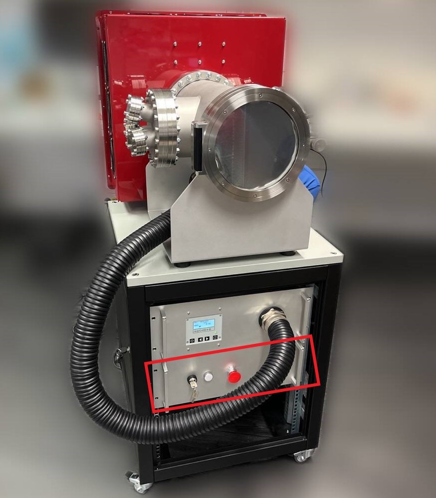
The interfaces at the front are (from left to right):
- the On-Off key lock switch (power On-Off the Thermal Control box)
- the status LED (white if powered on)
- the emergency stop button (power off the Thermal Control box)
Note
The Thermal Control emergency stop button only stops the Thermal Control box. The Thermal Vacuum box is powered separately.
Back
The front of the Thermal Control system is highlighted in the photo below.
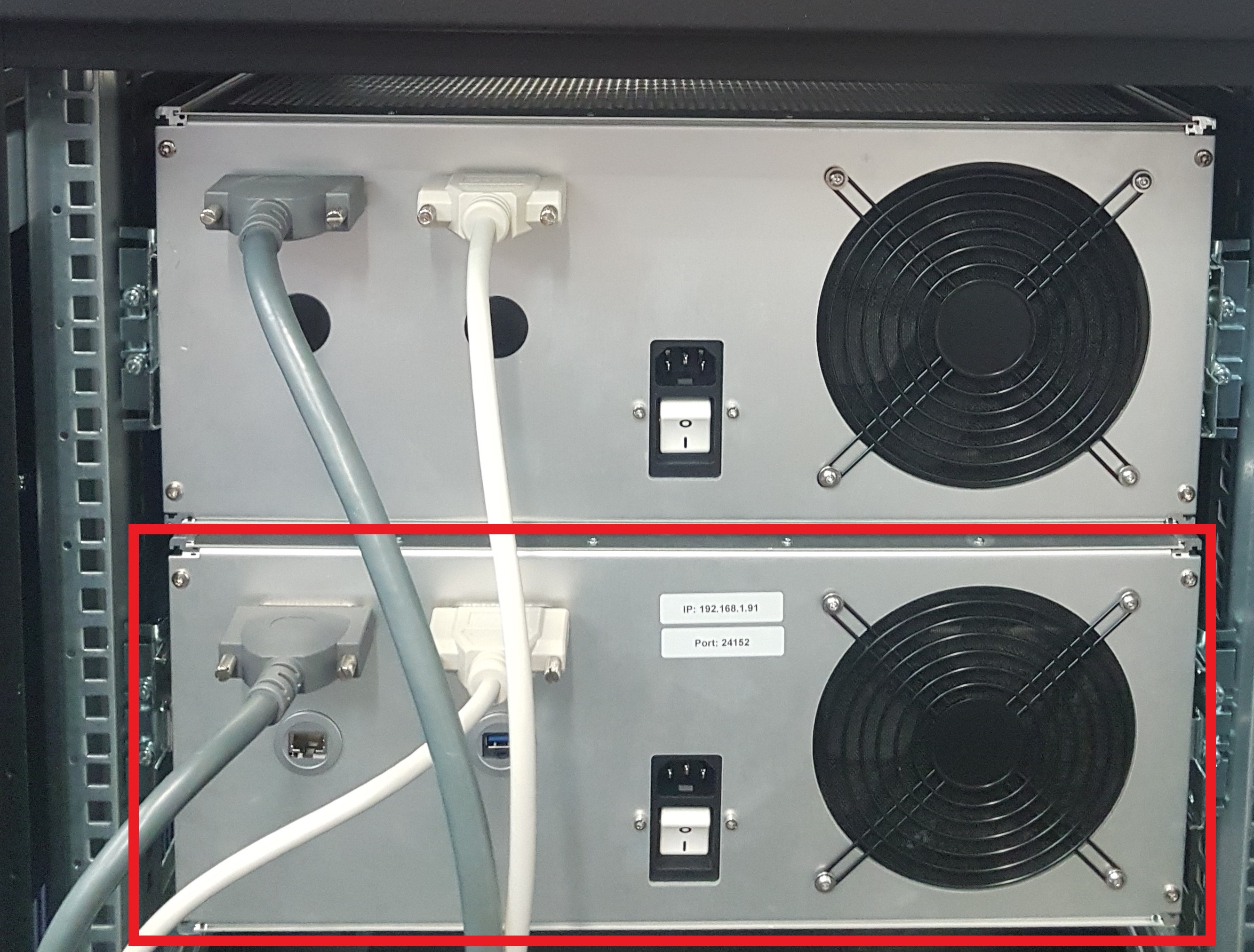
The interfaces at the back are (from left to right and top to bottom):
- D-Sub 25 Female connector (Power)
- D-Sub 25 Male connector (Signal)
- RJ45 feedthrough (Ethernet)
- USB 2.0 feedthrough (Updates and Debug)
- IEC 60320-1 C14 power entry connector with a switch
Danger - Fire & Electric Shock Hazards
Do not use other D-Sub 25 cables than the ones provided. Using different specs of cables can create fire hazards and/or loss of performances.
Danger - Fire & Electric Shock Hazards
Always attach the D-Sub 25 cables with the connector mounting screws. A misinserted cable can create fire hazards and/or damage XO-VAC+.
Danger - Electric Shock Hazard
Do not hot plug (insert or remove) the cables while XO-VAC+ is powered on. There is an electric shock risk for the user and the XO-VAC+ can get damaged.
Warning
The DB25 Male to Male Cable and the DB25 Female to Female Cable can expose you to chemicals including phthalates, which is known to the State of California to cause cancer and birth defects or other reproductive harm. For more information, go to www.p65warnings.ca.gov
Note
The USB feedthrough might look like a USB 3.0 port but it is connected to a USB 2.0 on the embedded server. The port speeds are therefore limited to the theoretical limits of USB 2.0 (480 Mbps).